

The Manley Ichiban and 500 watt, later known as 600 watt monoblocks, were built at the old VTL factory back before the Manley-VTL split-up that took place in 1993. They were at the time Manley's flagship models in the Designer's Reference Series. Both were 12-output tube designs. The Ichibans were triode strapped for about 200 watts output power (hence the smaller output transformer) and were found in both EL34 and KT90 tube complements. KT90's first showed up in 1990. The 500's or 600's were ultra-linear configured (with a much bigger output tranny) and used either GE 6550A's in the 500's before 1990 or KT90's in the 600's after 1990. The Input tube was always the 12AT7A or 6201. Some early models used the 12BH7A for driver tubes although most of the actual production models used 6350 driver tubes. Those two tube types have the grids and cathodes swapped on the pinout so make a big note that the 6350 and the 12BH7A are NOT interchangeable without reworking the circuit board!
Manley Ichibans sported solid Paduk wooden sides while the 500/600's had welded powdercoated steel side-members. Cool features of these amplifiers included the adjustable "slope" and "feedback" controls that allow the user to select different feedback capacitive and resistive values respectively. Also handy were the front panel mounted bias readout tipjacks and tube readout selector even though one still had to address the top deck of the amplifier to make the actual bias adjustments. See here how to do that. Many of the later Manley 600's and ICHIBANs had MIT-Multicaps. And some of them even had TRIODE / TETRODE switches. But none of them really ever got a proper owner's manual other than the generic info that was part of the VTL Book.
We still do perform warranty service on these old monsters, so if you need help with yours, please get in touch.
Top view:

Guts view, underside audio chassis showing tube location
Note for biasing: there are two 20 Ohms resistors in parallel which give 10 Ohms total value as the cathode resistor.
Front and angle views of Manley Reference 500.


Rear view of Manley Reference 500.
Blue binding post indicates around 1988 vintage, maybe early 1989.
Front and angle views of Manley Ichiban. Manley Ichiban has no gap between upper and lower chassis faceplates.


Top, rear, and side views of Manley Ichiban.


SPECIFICATIONS
Driver High current double 6350
Input l x 12AT7WA
Audio chassis on top, power supply chassis on bottom
The IEC detachable power cord is in the MIDDLE of the lower (power supply) chassis.
Input sensitivity: 0.750V
Input Impedance: 100 kOhm
Output load impedance: Factory set for 5 Ohms nominal
RCA Unbalanced input (sometimes had paralleled XLR connector)
Front Panel bias measurement and adjust
Mercury Magnetics power & output transformers
S/N ratio: -80 dB probably
Power consumption: enough to occasionally trip circuit breakers on turn-on
Large filter / reservoir capacitors
Factory set for 100V, 120V or 220-240VAC operation for original destination country's mains voltage.
Operating Mains Voltage changeable with power transformer re-wiring and fuse value change.
Mains Voltage Frequency:
Dimensions: bigger than a bread box
Each Chassis: 19" wide x 10" deep x 8.5" tall
The integral rack that holds the power supply on top of the audio chassis is 21" tall
That nets out to 19" wide x 10" deep x 21" tall per channel.Shipping weight: More than I can lift.
Specifications subject to change because they just might.
MANLEY VACUUM TUBE POWER AMPLIFIERS BIAS TRIMS
MANLEY Reference 600W or Ichiban - Built 1988 - 1993 (see picture below)
WHAT IS ADJUSTING THE BIAS?
All Manley amps have individual trimmers that are used to adjust each output tube's bias voltage. "Bias" is a negative voltage applied to the grid of each output tube which controls the quiescent, or standing, current draw of each tube. It is like setting the idle on your car. When we "measure the bias" we actually measure the voltage drop across the cathode resistor of that tube. When we "set or adjust the bias" we actually adjust the amount of negative voltage going to that tube's grid. But don't worry about all that if you don't want to... we just need you to take a reading with a meter and turn a trimpot to maintain optimum conditions for the tubes and verify that all the tubes are working fine.
WHY SHOULD I CHECK AND ADJUST THE BIAS?
1) Optimum bias provides the best balance of tube life and sound quality. Manley Lab's amp designs operate the tubes cool at low current so that the they typically last 5 years or longer if the bias is correct. Although, sometimes tubes have a short life and others may be fine for 20 or 30 years.
2) Individual bias trims eliminate the need for expensive matched sets of tubes or the need to replace all the tubes if one tube has a problem. We do recommend that tubes with "reasonably similar" characteristics are used and we batch and label them at the factory. When you need tubes, give us a call and let us know the number that is hand written on the tube as we have some special tube batching jigs we've been using for years. Yes, we do sell tubes - the good ones. After all, we're only as good as our worst tube....
3) The test points allow the user to check that each tube is working and that the amp is performing well (even if you don't intend to trim). Sometimes if one or two of the 12 tubes is dead the amp may be operational and sound pretty much OK, checking bias voltages will tell you more than your ears will sometimes. It also will tend to show a tube on its way out. You would see excessive voltage drift or a tube be out of trim range. This means replace that tube.
WHEN TO CHECK AND ADJUST BIAS
1) Definitely, when output tubes are changed.
2) On a regular schedule, you should at least check every three months but we recommend once a month.
3) Not every day and even once a week is probably excessive.
4) With new amps, the bias has certainly been factory adjusted but with all new tubes, it's a good idea to keep an eye on these newbies for the first month or so. If you replace some tubes that have not been "burnt in" or pre-tested or batched we also recommend you check the bias every few days for a few weeks watching out for "infant mortality".
5) If you see a red glow on the plate structure of the tube (inside the tube) then you need to check that tube's bias.
HOW TO CHECK BIAS
1) For this procedure you will need: a common voltmeter (a hand-held auto-ranging DMM (Digital MultiMeter)), and a small 1/8" flat screwdriver. With all tube power amps an output load is absolutely required. Easiest, is just leave your speaker connected to the amplifiers. If you have your amplifier on a test bench or away from the speakers you can use a 5 Ohm to 10 Ohm dummy-load resistor (5 or 10 watts is ok) attached across the binding posts. If you are using a low wattage dummy load resistor, do not play any tunes into the amplifier while it is hooked up this way! If you don't know what we're talking about, call for assistance or just leave your speakers hooked up.
2) The amp must be well warmed up (an hour will do). When you get ready to check the bias, there must no music playing through the amplifier. Silence please so you will get a valid measurement. Turn down the volume control on your preamp. (And hopefully you don't have any nasty DC offset off your preamplifier causing other problems... )
Note: an open input to an (high impedance) amplifier will pick up buzzing noise. A shorted input is great.
Hey, what a concept: Turn the INPUT MUTE ON!
3) Set the meter to read 'millivolts' DC or use the 2 Volt DC scale on a non-autoranging multimeter. The voltages you are looking at are under one volt.
4) Locate the two black bias measurement tip jacks on the faceplate marked "READ BIAS". Connect the red or ( + ) probe to one of the "Read Bias" test points and your black or ( - ) meter probe to the other "Read Bias" test point. It doesn't really matter which probe goes in which test point, but facing the front of the amplifier, you will get a positive reading if your red probe is in the right jack and the black meter probe is in the left jack. So do that.
5) The 12 position switch in the center of the black insert on the faceplate selects each tube for reading the bias. Start at the One O'Clock which corresponds to Tube #1. This switch reads like a clock so if you are selected at 6 O'Clock then guess what? You're at tube #6.
If the meter is on and set to read low volts it should read between positive 150 and 350 milli-volts DC or 0.150 to 0.350 volts DC. The value should correspond to the tube used.
EL-34 ———— 275 mV
6550 ———— 275 mV
KT-88 ———— 275 mV
KT-90 ———— 275 mV
If the voltage is too high, the tube will be running "hot", and will have a shorter life. In extreme cases a tube plate may glow "cherry red" - which usually kills the tube if it has been this way for more than a few minutes. Too low a voltage reading and the tube is "starved" and may cause some crossover distortion apparent during quiet passages. A higher voltage reading corresponds to a higher tube current draw. Ohm's law tells us V/R=I, so a reading of 275 mV DC divided by the 10 Ohm cathode resistor we are reading across gives us a quiescent (standing) current draw of 27.5 mA. Within a range of 20% there should be almost no change in the sound but probably a change in predicted tube life. Expect some drift - especially from month to month. 10% drift is quite normal and 20% begins to raise the warning flags. This is an early warning to watch this tube-- it may be beginning to go south.
4) Check the next tube(s) by selecting the next position on the switch. See the picture below for which tube corresponds to which adjustment trimmer. Continue until all points are checked. A tube that is "way out" often indicates it should be replaced or watched and checked over the course of a week or so.
5) NOTE: If you get some strange or erratic reading, swiftly switch back and forth the read bias switch cycling through each position rapidly. These switches are known to oxidise a little over the years. By switching rapidly through each position you stand a good chance of cleaning the silver contacts inside the switch. If your switch has bummed out entirely, you'll note the wires from the switch go down to the top of the amplifier deck and are plugged into more jacks. You can always use these jacks as secondary emergency readout points. They read left to right facing the front of the amplifier, ie; the left most jack corresponds to tube #1. Facing the FRONT! They are labeled in the picture below in VIOLET.
ADJUSTING BIAS
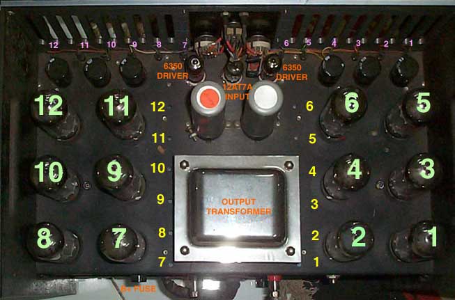
You need that small screwdriver now, so locate the holes in the top deck of the top chassis under which the trims are visible. They are small square blue trimmers with white centers with a slot for the screwdriver. In the picture below, they are labeled in YELLOW. The tubes themselves are labeled in GREEN. Be extra-careful not to miss the trimmer and short out the screwdriver to a circuit board trace. If you have a plastic tweaker, great, use it. These are single turn trimmers with a rotation of only 270 degrees. You should never force-turn one of these trimmers. See the picture below for where these trimmers are located and which one corresponds to which tube.
1) This is the same as the above check procedure but at each measurement you can adjust a trimmer to achieve the recommended voltage. You should perform a check regularly but only adjust or trim the bias on tubes that are reasonably out of calibration or when tubes are changed.
2) Repeat as necessary. You have to go back and do it again if any of the trimmers needed major tweaking. You may notice that the first points have changed. There is some interaction. If just some minor 10% or 20% tweaks were needed you won't see much change.
3) Done - Sit back and enjoy some music. That wasn't too tough.
4) With new tubes, we recommend checking the bias daily for the first week of operation, and once a month thereafter.
PICTURE OF MANLEY REFERENCE 600W OR ICHIBAN TUBE AND TRIMMER LOCATION

TUBES in GREEN
BIAS ADJUSTMENT TRIMPOTS IN YELLOW
EMERGENCY BIAS READOUT JACKS IN VIOLET
BIAS and TUBE PROBLEMS
The most common problem is that you tend to see all the tubes drifting up and down together. This is caused by AC power line fluctuations. Probably nothing we can do about that.
Goofy and erratic readings: see above about flaky bias select switch.
Sometimes you may see one test point only read "Zero" no matter where the trimmer is tweaked. Usually this indicates a dead tube. 9 times out of 10 replacing the tube solves that. Sometimes a tube is not too graceful as it dies - it shorts out and burns out the 10 Ohm cathode resistor. You can check the state of these cathode resistors by much like measuring bias except that the amplifier is OFF and the meter is set to read OHMS. Each should read close to 10Ohms. If one reads much higher, in that case a technician, with a soldering iron and a few 10 Ohm 5 watt resistors is needed. Easy fix. Better to burn up a resistor than a transformer. It does double duty as a fuse. Usually one of the "real" fuses goes first but not always.
"Don't worry, its rare, department"
If all the tubes suddenly start glowing bright cherry red it means the amp has lost the bias power supply. Turn off the amp and get it to a technician. Suggest "that he should remove the tubes before turning the amp on".
A few other obvious tube symptoms
"It makes a lot of noise if I tap this tube". It happens. The first preamp tube (12AT7) will generally be somewhat more microphonic because it deals with the smallest signals and amplifies most. It is a judgment call whether any of the tubes have become too microphonic. You may need several tubes to "pick out" the best one.
"This tube has turned white and cloudy". We like to joke that the vacuum leaked out. Air has gotten into the tube, probably through a small crack in the glass. Its not at all well - replace it. It's a goner.
"This seems like a lot of maintenance and technical mumbo-jumbo". Its all pretty easy really and on your own schedule. Remember that in the "old days" your folks could fix the family TV by changing a tube. This is the next easiest thing to changing a light bulb. You might also consider that when a solid state amp has a problem - it's FED-EX time. Your local tech wizard probably doesn't have the schematics and parts, and you probably just lost a few speakers in the process. Could be worse. Most people have less technical problems with our amps than with their CD player(s).